
The aim of this project is to display eyes on the screen and give the senseBox a bit of personality. The eyes should follow your finger with their gaze, which we implement with the help of the ToF distance sensor. The eyes can also blink, smile, change their shape and mood. Let’s try it out!
Setup
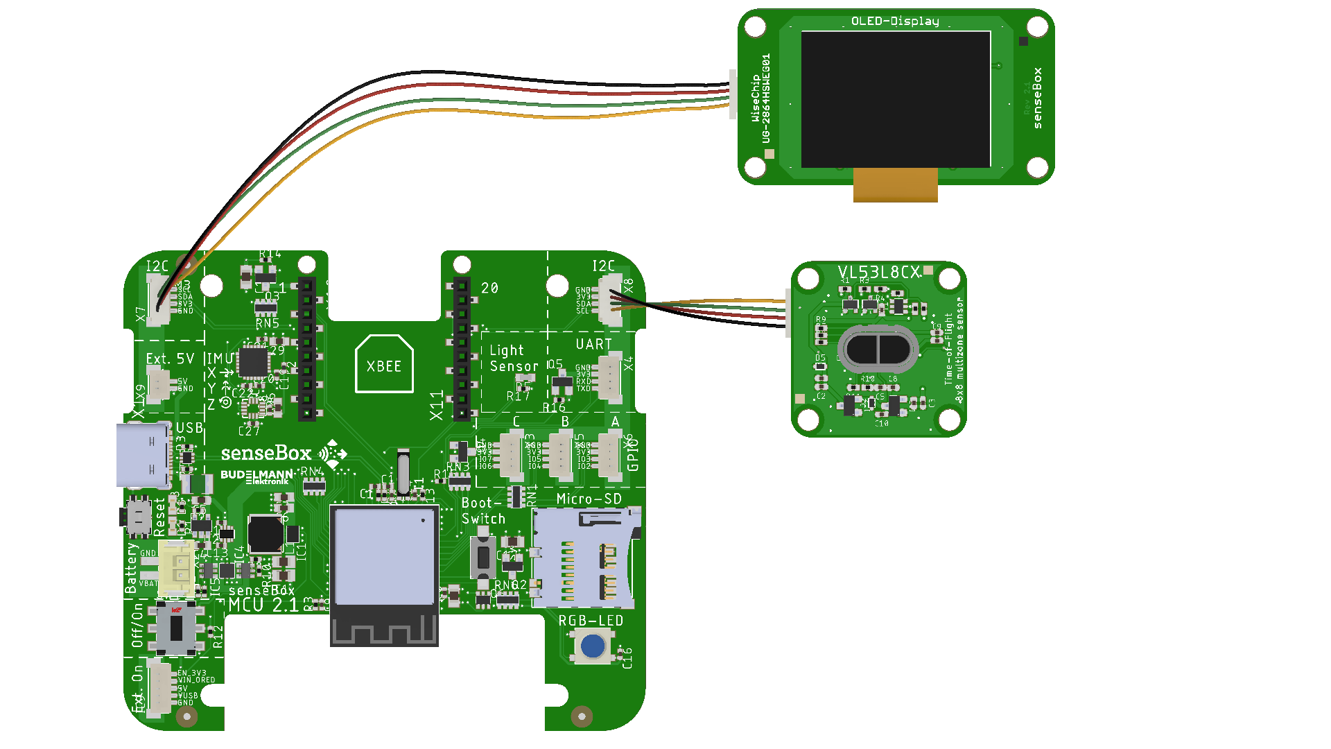
Connect the display to an I2C port using one of the QWIIC cables. Connect the ToF sensor to the other I2C port in the same way. Make sure that the sensor and display are facing in the same direction and are as close to each other as possible. In addition, the side of the ToF sensor labelled ‘VL53L8CX’ should be facing upwards.
Programming
Use either the senseBox-Blockly code editor or the Arduino IDE to do the programming for this project. First, in the ‘Hello World…Robot!’ section, we program the robot eyes to appear on the senseBox display and then blink at irregular intervals. Next, we use the measurement data from the ToF distance sensor to make the eyes follow the position of the finger. In the third section, we program the mood of the eyes to change depending on the distance. Let’s get started!
Step 1: Hello World…Robot!
Import libraries, create variables
First of all, we need the appropriate libraries (= software libraries) for the project. If you are working in Blockly’s code editor, these are already pre-installed. In the Arduino IDE, you will need to import them. (Not sure what libraries are and how to import them? No problem! You can find more information here: Adding an Arduino software library)
To easily integrate the ToF distance sensor, we use the ‘STM32duino VL53L8CX’ software library (from STMicroelectronics). For the display, we use the ‘Adafruit_SSD1306’ library (from Adafruit). Install both via the Library Manager of the Arduino IDE.
To be able to use these libraries in the code, we still need to integrate them accordingly (also in the Blockly Code Editor):
#include <Wire.h>
#include <Adafruit_GFX.h> // http://librarymanager/All#Adafruit_GFX_Library
#include <Adafruit_SSD1306.h> // http://librarymanager/All#Adafruit_SSD1306
#include <vl53l8cx.h>
To use the sensor and display, we also need to set them up, including defining the height and width of the display:
VL53L8CX sensor_vl53l8cx(&Wire, -1, -1);

#define SCREEN_WIDTH 128
#define SCREEN_HEIGHT 64
#define OLED_RESET -1
Adafruit_SSD1306 display(SCREEN_WIDTH, SCREEN_HEIGHT, &Wire, OLED_RESET);
For the eyes, we use the RoboEyes library (from FluxGarage). This must be downloaded and installed manually for the Arduino IDE: RoboEyes download page. It is already pre-installed in the Blockly code editor. We also integrate the library using the ‘#include’ command and then create an instance to use it:
#include <FluxGarage_RoboEyes.h>
roboEyes roboEyes; // create RoboEyes instance
Setup and Startup
In the setup() function, we start the ToF sensor, the display and the Robo-Eyes and define, among other things, the frequency, resolution and data rate. (As these functions are not specific to this project, we will not go into detail here. If you would like more information, the Arduino documentation will help.)
void setup() {
  Serial.begin(9600);

  delay(1000);

  Wire.begin();
  Wire.setClock(1000000); //Sensor has max I2C freq of 1MHz
  sensor_vl53l8cx.begin();
  sensor_vl53l8cx.init();
  sensor_vl53l8cx.set_ranging_frequency_hz(30);
  sensor_vl53l8cx.set_resolution(VL53L8CX_RESOLUTION_8X8);
  sensor_vl53l8cx.start_ranging();
  Wire.setClock(100000); //Sensor has max I2C freq of 1MHz

  // Startup OLED display
  if(!display.begin(SSD1306_SWITCHCAPVCC, 0x3D)) { // Address 0x3C or 0x3D
    Serial.println(F(‘SSD1306 allocation failed’));
    for(;;); // Don't proceed, loop forever
  }

  // Startup robo eyes
  roboEyes.begin(SCREEN_WIDTH, SCREEN_HEIGHT, 100); // Screen width, screen height, maximum frame rate
Automatic eye movements
Now there is only one thing left to do to test our RoboEyes: In the infinite loop, we define that the type and position of the eyes on the display should be updated in each run:
void loop() {
  roboEyes.update(); // Update the eyes
}
Load the sketch onto your senseBox: The eyes should now be displayed.
The eyes still appear ‘lifeless’ because they do not change during the course of the programme. The RoboEyes library offers numerous options for changing this. We will start by making the eyes blink. To do this, we simply add the ‘autoblinker’ to the setup() function:
roboEyes.setAutoblinker(ON, 3, 2); // Blinks at an interval of (3) seconds with a variation of (2) seconds
Load the sketch onto your senseBox and try it out!
Step 2: Eyes follow the movement
Now we want the eyes to follow our finger. To do this, we use the ToF sensor. This can measure not just one distance, but 8x8 distances in a square. The eyes should always look where the nearest object (or finger) is. So we always measure which of the 64 distances is the shortest, and the eyes should then move in that direction.
Interval
To implement this, the distance should be measured regularly in the loop() function and the position of the eyes updated accordingly. To ensure that they move smoothly and are not updated in every frame, we define an interval of 75 milliseconds. Instead of using the delay() function from the standard Arduino library, we define our own measurement interval. The delay() function ensures that the programme code is completely interrupted; this can be better solved by using a self-defined measurement interval. To do this, three additional variables are defined at the beginning of our programme, before the setup() and loop() functions. The variables store the time since the start of the interval, the length of the interval and the current runtime of the programme.
long update_interval = 75; // Interval of 75 milliseconds
long start_time = 0;
long actual_time = 0;
The Arduino function millis() returns the number of milliseconds since the senseBox was started. This function can be used to create an if query that becomes valid when 75 milliseconds have elapsed.
void loop() {
  start_time = millis();
  if (start_time > actual_time + update_interval) {
    // 75 milliseconds have passed
    actual_time = millis();
  }
  roboEyes.update(); // Update the eyes
}
Measuring distances with the ToF sensor
Within this interval, we now want to measure the distances and find the lowest one. To do this, we adapt the function found in the ToF manual to our case. It is important that we save not only the shortest distance (min_distance) but also the position of the pixel with the shortest distance (min_index). To do this, we read out the data and save it as ResultsData. We then go through the data in a for loop to find and save the shortest distance:
VL53L8CX_ResultsData Result;
uint8_t NewDataReady = 0;
uint8_t status;

Wire.setClock(1000000); //Sensor has max I2C freq of 1MHz
status = sensor_vl53l8cx.check_data_ready(&NewDataReady);
Wire.setClock(100000); //Sensor has max I2C freq of 1MHz

if ((!status) && (NewDataReady != 0)) {
  Wire.setClock(1000000); //Sensor has max I2C freq of 1MHz
  sensor_vl53l8cx.get_ranging_data(&Result);
  Wire.setClock(100000); //Sensor has max I2C freq of 1MHz
  // Find the pixel with the shortest distance
  int min_index = 0;
  uint16_t min_distance = (long)(&Result)->distance_mm[0];
  for (int i = 1; i < 64; i++) {
	if ((long)(&Result)->distance_mm[i] < min_distance) {
      min_distance = (long)(&Result)->distance_mm[i];
      min_index = i;
    }
  }
Adjusting the direction of the RoboEyes
The RoboEyes indicate their position using abbreviated compass directions, with ‘DEFAULT’ describing the centre. The directions are therefore: N, NE, NW, W, E, S, SE, SW. In the previous step, we determined the index of the shortest distance. How can we now translate this into one of the directions?
It may help to visualise the results. The index gives us a number that represents a value in an 8x8 field. We have to decide how to divide the field, i.e. where N (north) is. Since 8 cannot be divided by 3, this cannot be done evenly. To keep the eyes in the centre as little as possible, we want to define the outer ends as larger. Here is a colour-coded division of the 8x8 field, where red stands for W(est) and green for E(ast), for example.
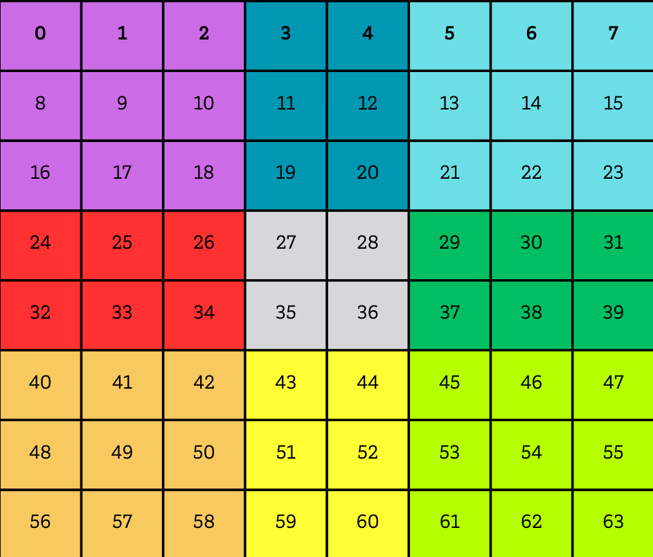
One way to translate the index into a cardinal direction is via the row and column. A combination of row and column can be used to clearly determine which field the eyes should move to. We calculate the row by dividing the index by 8. We obtain the column from the remainder of the division by 8. In many programming languages, this can be easily calculated with ‘%’, so it looks like this:
    int row = min_index / 8;
    int col = min_index % 8;
We can translate the viewing direction from the row and column using a series of if-else queries (you can find information about ‘if-then’ conditions on the learning card GI02). We also want the eyes to only follow the movement if the finger is close enough. So we add the condition that the distance must be less than 400 mm. Try defining the if-else queries yourself! Then you can compare them with our suggestion:
	unsigned char direction;

	if (row == 3 || row == 4) {
	  if (col == 3 || col == 4) {
		  direction = DEFAULT;
	  } else if (col < 3) {
		  direction = W;
	  } else {
		  direction = E;
	  }
	} else if (row < 3) {
	  if (col == 3 || col == 4) {
		  direction = S;
	  } else if (col < 3) {
		  direction = SW;
	  } else {
		  direction = SE;
	  }
	} else {
	  if (col == 3 || col == 4) {
		  direction = N;
	  } else if (col < 3) {
		  direction = NW;
	  } else {
		  direction = NE;
	  }
	}
void loop() {

  start_time = millis();
  if (start_time > actual_time + update_interval) {
    actual_time = millis();
    VL53L8CX_ResultsData Result;
    uint8_t NewDataReady = 0;
    uint8_t status;

    Wire.setClock(1000000); //Sensor has max I2C freq of 1MHz
    status = sensor_vl53l8cx.check_data_ready(&NewDataReady);
    Wire.setClock(100000); //Sensor has max I2C freq of 1MHz

    if ((!status) && (NewDataReady != 0)) {
      Wire.setClock(1000000); //Sensor has max I2C freq of 1MHz
      sensor_vl53l8cx.get_ranging_data(&Result);
      Wire.setClock(100000); //Sensor has max I2C freq of 1MHz
      int min_index = 0;
      uint16_t min_distance = (long)(&Result)->distance_mm[0];
      // Finden des Pixels mit der geringsten Distanz
      for (int i = 1; i < 64; i++) {
        if ((long)(&Result)->distance_mm[i] < min_distance) {
          min_distance = (long)(&Result)->distance_mm[i];
          min_index = i;
        }
      }

      if (min_distance < 400) {
        int row = min_index / 8;
        int col = min_index % 8;
 // Herausfinden der Blickrichtung
        unsigned char direction;

        if (row == 3 || row == 4) {
          if (col == 3 || col == 4) {
              direction = DEFAULT;
          } else if (col < 3) {
              direction = W;
          } else {
              direction = E;
          }
        } else if (row < 3) {
          if (col == 3 || col == 4) {
              direction = S;
          } else if (col < 3) {
              direction = SW;
          } else {
              direction = SE;
          }
        } else {
          if (col == 3 || col == 4) {
              direction = N;
          } else if (col < 3) {
              direction = NW;
          } else {
              direction = NE;
          }
        }

        roboEyes.setPosition(direction);

      }
    }
  }

  roboEyes.update(); // Aktualisieren der Augen

}
Transfer the code to your senseBox and try it out!
Step 3: Change the mood of the RoboEyes
The mood of the RoboEyes can be changed with the function roboEyes.setMood(). We can incorporate this into our programme in various ways.
One easy way is to have the RoboEyes change their mood directly based on the measured distance. We can implement this with if-else statements. If the eyes ‘see’ something at a distance of up to 120 mm, they are happy; at a distance of up to 400 mm, they are neutral; and otherwise, they are tired:
//Set mood depending on measured distance
if (min_distance < 120) {
    roboEyes.setMood(HAPPY);
} else if (min_distance < 400) {
    roboEyes.setMood(DEFAULT);
} else {
    roboEyes.setMood(TIRED);
Make sure you place these lines of code within the status query if ((!status) && (NewDataReady != 0)) { so that the variables min_distance and min_index can be read at this point. Then try it out right away!
Extras & Further Ideas
The RoboEyes software library offers several additional functions. First of all, you can define how the eyes of your senseBox should look. All values are specified in pixels. As a reminder, the senseBox display is 128x64 pixels in size. Here are the functions you can use to change the shape of the eyes:
  roboEyes.setWidth(36, 36); // byte leftEye, byte rightEye
  roboEyes.setHeight(36, 36); // byte leftEye, byte rightEye
  roboEyes.setBorderradius(8, 8); // byte left eye, byte right eye
  roboEyes.setSpacebetween(10); // int space between eyes -> can also be negative
There are also other functions, including animations that can be played or idle mode:
  roboEyes.anim_confused(); // confused – eyes move left and right
  roboEyes.anim_laugh(); // laugh – eyes move up and down
  roboEyes.setIdleMode(ON, 2, 2); // Start idle animation (eyes look in random directions) -> ON/OFF: Switch on/off, number1: Interval in seconds during which the eye position changes, number2: Variation in the interval in seconds
Here are a few ideas for what you can try next:
- Clicking the button on the senseBox causes the eyes to start laughing with
roboEyes.anim_laugh(). - If the senseBox has not seen anything for a while (distance less than 400 mm), it goes into ‘idle mode’ with
roboEyes.setIdleMode(). In this mode, it automatically changes its line of sight repeatedly, looking around in a relaxed manner. - If the distance and thus the mood of the eyes changes very often in succession, the eyes become briefly confused with
roboEyes.anim_confused().
Feel free to get creative and adjust the eyes so that they suit you and your senseBox. Have fun!
Complete code
You can find the complete code here: Project code on Github